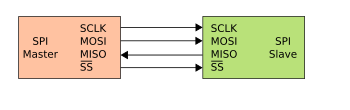
SCLK – Serial
Clock (that is an output of the master)
MOSI – Master Output; Slave Input
MISO - Master Output; Slave
Input
SS –
Slave Select (active low)
How SPI communication happens
- Master should configure a clock that the slave device supports. (Typically the frequency range is from 1-100MHz)
- Master should transmit the appropriate CS signal to the slave device.
- A full duplex transmission can be supported since separate lines for maser input and output are available.
- Depending on the application we can decide on the method that we want to use in our application (full duplex or half duplex).
- When data transmission happens, SPI clock should be available. Otherwise data transmission will not happen properly. When no data is transmitted clock should be stopped.
Clock polarity and phase

Clock phase is zero
Data are read at
the rising edge of the clock and data are written at the falling edge of
the clock
Clock phase is one
Clock phase is one
Data are read at the
falling edge of the clock and data are written at the falling edge of
the clock.
When clock polarity is one
Clock phase is zero
Data are read at the falling edge of the clock and the data are written at the rising edge of the clock.
Clock phase is one
Data are read at the rising edge of the clock and the data are written at the falling edge of the clock.
Clock phase is zero
Data are read at the falling edge of the clock and the data are written at the rising edge of the clock.
Clock phase is one
Data are read at the rising edge of the clock and the data are written at the falling edge of the clock.
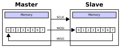
When data transmission happens, normally MSB is put to the data line first.(shown in the above figure)
Reference: Wikipedia
article on Serial Peripheral Interface Bus
No comments:
Post a Comment