Wednesday, July 4, 2012

i


Though we are interested in iPhones, MacBooks and many other productions by Apple, Objective-C is not a very familiar language for most of us. Though it’s an extension of C language, it has many differences in syntax. 

This is the main programming language used by Apple in their OS X (Mac OS X) and iOS (iPhone OS) and this is based on the language Smalltalk which is one of the very first object oriented languages.

So, Objective-C has the features like many other object oriented languages. This consists of a library of objects, a suite of development tools and a runtime environment.

Tuesday, July 3, 2012

Hardware Virtualization

You may be interested in working with multiple operating systems at the same time. Sometimes it may be a requirement when you are doing a particular job.
The simplest solution is to have a virtual machine. Being in a windows environment, if you want to run Mac OS in a virtual machine you may encounter several problems. If your processor supports hardware virtualization, you can try Mac OS in your VM ware with fewer efforts. But if it doesn’t ……
Since I had to face this problem, I read some articles to learn about hardware virtualization. Below you can read some facts about hardware virtualization.
Hardware virtualization is a technology that is heavily used in server platforms due to its ability to provide with facilities to perform multiple tasks on a single processor without requiring separate software applications.
Hypervisor; the software that is used to control the processor, memory and other resources allows multiple operating systems to run on the same platform without changing the existing operating system. So, it is also called as virtual machine manager.

Where do we use hardware virtualization?

  • When you want to play around with an operating system, the best thing is to use a virtual machine. Damaging the OS running in the virtual machine may not damage the host system in your computer.
  • This can be used in kernel developments.
  • As mentioned above, this can be used in server platforms.
  • You can copy your virtual machine from one computer and place it in a different computer, very easily.

Saturday, June 30, 2012

MSR EEE (Magnetic Stripe Reader End to End Encryption) Implementation

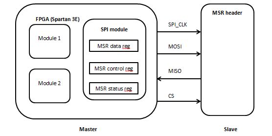
This is a brief article about the SPI communication that I implemented, between the FPGA and the MSR EEE chip. 

3 registers were defined
·         msr_data_reg – 8 bit register
       Used to store data to be written to the device and read from the device
·         msr_control_reg - 8 bit register
       Used to store control information. Used three bits of the register .
       0th bit – write bit
       1st bit – read bit
       2nd bit – chip select bit
·         msr_status_reg – 8 bit register
      Used to store the status of the device. (To check data availability) When data are available, DAV pin of
      the MSR chip goes to logic high.

Importance of DCM (Digital Clock Manager)

  •  It’s an open core freely available with Xilinx.
  • This is used to implement delay locked loops, digital frequency synthesizers, digital phase shifters and digital spread spectrums.
When implementing the SPI communication, I made use of the DCM core.


Reason for the usage – For the proper communication between the MSR header and the FPGA, we need to have a good clocking throughout the operation. Due to the propagation delays of wire connections in the circuits, exact clocks may not reach the device. To address this issue, we can use the DCM core. Then it will manage proper propagation of clock frequency to the devices.

VHDL

During my internship period, I got the chance to implement an SPI Communication between an FPGA (Spartan 3E) and an MSR(Magnetic Stripe Reader) chip.

In the earlier blog post, I mentioned some important information about SPI communication.
Here, I will mention some brief information about my MSR implementation. I used VHDL as the language. In developing the project and used Xilinx ISE Design Suite 13.3.


"The VHSIC Hardware Description Language is an industry standard language used to describe hardware from the abstract to the concrete level. VHDL resulted from work done in the  ’ 70s and early  ’ 80s by the U.S. Department of Defense. Its roots are in the ADA language, as will be seen by the overall structure of VHDL as well as other VHDL statements. VHDL usage has risen rapidly since its inception and is used by literally tens of thousands of engineers around the globe to create sophisticated electronic products.

VHDL is a powerful language with numerous language constructs that are capable of describing very complex behavior. Learning all the features of VHDL is not a simple task."

Taken from : VHDL: Programming by Example by Douglas L. Perry

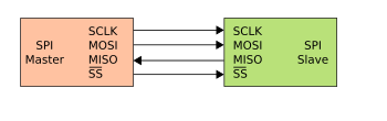
SPI (Serial Peripheral Interface) Communication


SCLK – Serial Clock (that is an output of the master)
MOSI  – Master Output; Slave Input
MISO  -  Master Output; Slave Input
SS       – Slave Select (active low)

How SPI communication happens

  • Master should configure a clock that the slave device supports. (Typically the frequency range is from 1-100MHz)
  • Master should transmit the appropriate CS signal to the slave device.
  • A full duplex transmission can be supported since separate lines for maser input and output are available.
  • Depending on the application we can decide on the method that we want to use in our application (full duplex or half duplex).
  • When data transmission happens, SPI clock should be available. Otherwise data transmission will not happen properly. When no data is transmitted clock should be stopped.

Clock polarity and phase


When clock polarity is zero
  Clock phase is zero
      Data are read at the rising edge of the clock and data are written at the falling edge of the clock
  Clock phase is one
      Data are read at the falling edge of the clock and data are written at the falling edge of the clock.

When clock polarity is one
   Clock phase is zero
      Data are read at the falling edge of the clock and the data are written at the rising edge of the clock.
   Clock phase is one
      Data are read at the rising edge of the clock and the data are written at the falling edge of the clock.


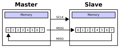
File:SPI 8-bit circular transfer.svg


When data transmission happens, normally MSB is put to the data line first.(shown in the above figure)

Note : Figures are take from Wikipedia
Reference: Wikipedia article on Serial Peripheral Interface Bus
        http://en.wikipedia.org/wiki/Serial_Peripheral_Interface_Bus  [Accessed date: 30-06-2012]

Sunday, June 17, 2012

How to build a character driver

First we include the functions open, release, read, write and ioctl (input output control) to the driver.

<chardev.c>
1:  #include <linux/init.h>               //specify initialization and cleanup functions  
2:  #include <linux/module.h>          //definitions of symbols and functions  
3:  #include <linux/fs.h>               //allocating and freeing device numbers  
4:  #include <linux/errno.h>          //error codes  
5:  #include <asm/uaccess.h>          //user space access (to move data to and from user space)  
6:  #define DEV_MAJOR          223  
7:  #define     DEV_MINOR          0  
8:  char my_data[80]="first chardevice";   
9:  int dev_open(struct inode *inode,struct file *filep);  
10:  int dev_release(struct inode *inode,struct file *filep);  
11:  ssize_t dev_read(struct file *filep,char *buff,size_t count,loff_t *offp );  
12:  ssize_t dev_write(struct file *filep,const char *buff,size_t count,loff_t *offp );  
13:  int dev_ioctl(struct inode *inode, struct file *filep,unsigned int cmd, unsigned long arg);  
14:  struct file_operations my_fops={  
15:       .open = dev_open,  
16:       .release = dev_release,       
17:       .read = dev_read,  
18:       .ioctl = dev_ioctl,  
19:       .write = dev_write,            
20:  };  
21:  int dev_ioctl(struct inode *inode, struct file *filep,unsigned int cmd, unsigned long arg)  
22:  {  
23:       if (cmd==10)  
24:            printk("\nIOCTL function\n");            
25:            return 10;  
26:  }  
27:  int dev_open(struct inode *inode,struct file *filep)  
28:  {  
29:       printk("\ndev open\n");  
30:       return 0;  
31:  }  
32:  int dev_release(struct inode *inode,struct file *filep)  
33:  {       
34:       printk("\ndev release\n");  
35:       return 0;  
36:  }  
37:  ssize_t dev_read(struct file *filep,char *buff,size_t count,loff_t *offp )  
38:  {       
39:       if ( copy_to_user(buff,my_data,strlen(my_data)) != 0 )  
40:            printk( "Kernel -> userspace copy failed!\n" );  
41:       else  
42:            printk("reading is successful");  
43:       return strlen(my_data);  
44:  }  
45:  ssize_t dev_write(struct file *filep,const char *buff,size_t count,loff_t *offp )  
46:  {       
47:       if ( copy_from_user(my_data,buff,count) != 0 )  
48:            printk( "Userspace -> kernel copy failed!\n" );  
49:       else  
50:            printk("writing is successful");  
51:       return 0;  
52:  }  
53:  static int dev_init(void){  
54:       printk("\nmodule init\n");  
55:       if(register_chrdev(DEV_MAJOR,"chardev",&my_fops)){  
56:            printk("<1>failed to register");  
57:       }  
58:       return 0;  
59:  }  
60:  static void dev_exit(void){  
61:       printk("\nmodule exit\n");  
62:       unregister_chrdev(DEV_MAJOR,"chardev");  
63:       return 0;  
64:  }  
65:  module_init(dev_init);  
66:  module_exit(dev_exit);  
67:  MODULE_LICENSE("GPL");  
68:  MODULE_AUTHOR("SUNETH <sunethe@zone24.com>");  
69:  MODULE_DESCRIPTION("CHAR DRIVER");  
Major and minor numbers

  • Normally character drivers are listed with ‘c’ letter.
  • ls –l’ command will list devices. There you can find two numbers. One is called the major number and the other is the minor number.
  • Major number is used to identify the device that is associated with the device driver.
  • Minor number is used by the kernel to determine the driver that is exactly referring at the moment.
Char device registration, is done when the module is inserted to the kernel.
Unregistering the device the char driver happens when the module is removed from the kernel.
Unregistering the driver allows us reusing the device numbers that we used.
The functionality of the module_init(); and module_exit(); was describes in the previous article.

open method

Prototype for the open method.
int (*open)(struct inode *inode, struct file *filp);

release method

Prototype for the open method.
int scull_release(struct inode *inode, struct file *filp);

read method

Prototype for the read method.
ssize_t read(struct file *filp, char __user *buff, size_t count, loff_t *offp);


write method

Prototype for the write method.
ssize_t write(struct file *filp, const char __user *buff, size_t count, loff_t *offp);


How to test the driver
1:  #include <stdio.h>  
2:  #include <unistd.h>  
3:  #include <sys/types.h>  
4:  #include <sys/stat.h>  
5:  #include <fcntl.h>  
6:  #include <sys/ioctl.h>  
7:  #include <string.h>  
8:  int main()  
9:  {  
10:       int fd=0,ret=0,iot=0;  
11:       char buff[80],wrbuff[80],iob[80];       
12:       char wbuff[80]="writing data     ";   
13:       int chk=0;  
14:       fd=open("/dev/chardev",O_RDWR);          //open the device for read and write  
15:       printf("\nfd :%d\n",fd);  
16:       memset(buff, 0, sizeof(buff));  
17:       ret=read(fd,buff,10);                    //read the device  
18:       buff[ret]='\0';  
19:       chk=write(fd,wbuff,strlen(wbuff));     //write to the device  
20:       memset(wrbuff, 0, sizeof(wrbuff));  
21:       ret=read(fd,wrbuff,80);                    //read again  
22:       buff[ret]='\0';  
23:       memset(iob, 0, sizeof(iob));          //call ioctl  
24:       iot=ioctl(fd,10,iob);  
25:       printf("\n%d\n",iot);  
26:       printf("\nbuff: %s ;length: %d bytes\n",buff,ret);  
27:       printf("\nbuff: %s ;length: %d bytes\n",wrbuff,ret);  
28:       close(fd);                              //close the device  
29:  }  

Creating a device file

This is special file that is usually created in /dev
‘mknod path type major minor’
Eg: ‘mknode /dev/chardev c 235 0
   ‘chardev’ -  device file name
   ‘c’ indicated that this is a char driver
   ‘235’ and ‘0’ – major number and minor number respectively.

Compile the driver
  • Create the  Makefile
<Makefile>
1:  obj-m := chardev.o  
2:  KVERSION =$(shell uname -r)  
3:  all:  
4:     make -C /lib/modules/$(KVERSION)/build M=$(PWD) modules  
5:  clean :  
6:     rm -rf *.o  

            In the terminal  $ make’
            This will create ‘chardev.ko’ file.
  • Load the module
           ‘# insmod chardev.ko’
  • Run the test application
            First compile the test application and run the executable file ‘# ./a.out
            This will give you the results as given by the test application.
  • Remove the module
           ‘# rmmod chardev